lesson 02 - Servo control
posted: Wed, Jun 14, 2023 |
tagged: projects | dev | electronics | fec
return to project home | resources
Code and reference Fritzing diagrams
Part 1 - Servo time
References
Pulse Width Modulation (PWM)
Pulse Width Modulation (PWM) is is better described in this quick article:
By comparison to lesson 1, when we set led.value = True, we essentially set the pin to high (on) sending voltage through the indicated GPIO pin. With PWM, we are quickly cycling the pin state at a specific frequency and at a defined duty cycle.
What are some of PWMs applications?
- Drive a buzzer at varying degrees of loudness
- Control the speed of a motor
- Provide an analog output
- Generate audio signals
- Telecommunications messages
- And yes, control a servo! Now let's do this!
Approach
- We'll connect a Servo to our Pico and manipulate the angle of the servo horn
- Attach one of the horn blades to your servo to better see the articulation
- We'll feed the servo a full 5 volts from the Pico (via VBUS)
- VBUS - the VBUS pin on the Pico passes the full 5V from the USB connector to connected devices, rather than 3.3V that can be sourced from the other GPIO pins
Wiring
Note, in the below diagram the rails are reversed compared to the breadboard received in the kit. Please wire appropriately. Also the servo connecting wires do not match that of the diagram, see the notes below for color coordination between the connections.
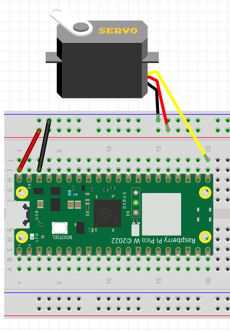
- Attach your pico to the breadboard
- Connect VBUS to the positive (+) rail of the breadboard
- Connect GND to the negative (-) rail of the breadboard
- Connect a black wire from the brown servo connector to the negative rail
- Connect a red wire from the red servo connector to the positive rail
- Connect a blue wire from the orange servo connector to GP16
Libraries
We'll need to include the adafruit_motor library on our Pico to more easily drive our servo motor. In the Adafruit official bundle, you'll find a folder named adafruit_motor in the lib folder. Copy the adafruit_motor folder and its contents onto your Pico in the lib folder. This will make the library available for import on the Pico.
Code
# Import libraries
import time
import board
import pwmio
from adafruit_motor import servo

# Create a PWM object and myServo for operating device (connected via GP16)
pwm = pwmio.PWMOut(board.GP16, duty_cycle=2 ** 15, frequency=50)
myServo = servo.Servo(pwm)

# Loop over a range of sweeping positions with a short sleep to keep movements fluid
while True:
    for angle in range(0, 180, 5):
        myServo.angle = angle
        time.sleep(0.05)
    for angle in range(180, 0, -5):
        myServo.angle = angle
        time.sleep(0.05)
Part 2 - not a crock Pot
References
Potentiometers
A potentiometer ("pot" for short) is an analog device that acts as a variable resistor. Depending on the position of the wiper, the amount of current resisted changes. We can read the amount via an analog input pin with the help of the AnalogIO library.
Approach
We will modify the above program to read in the values from the pot and adjust the servo positioning as a result. We'll add in a slight delay to keep this from getting too jerky.
- Add a 10k pot to the project to control the servo
Wiring
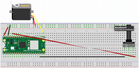
With the wiring from Part 1 of this project in place, we'll expand by adding the following patches to our board.
- Connect a pot so the wiper points towards the opposite side of the pico from our existing connections leaving 1 row vacant on the bottom of the breadboard
- Connect a black wire from GND to the left-most / highest pin of the pot
- Connect a white wire from GP26 (also known as ADC0) to the middle pin of the pot
- ADC is an analog to digital converter, and GP26 is ADC0. To CircuitPython, this appears as A0 as you'll see in the code below. Only certain pins on the Pico are capable of ADC functionality.
- Connect a red wire from 3V3 to the right-most / lowest pin of the pot
Code
# Import libraries
import time
import board
import pwmio
from adafruit_motor import servo
from analogio import AnalogIn

# Create a PWM object and myServo for operating device (connected via GP16)
pwm = pwmio.PWMOut(board.GP16, duty_cycle=2 ** 15, frequency=50)
myServo = servo.Servo(pwm)

# Create a potentiometer ("pot") object
potentiometer = AnalogIn(board.A0)

# Loop while reading the value of the pot and adjusting the servo
# with a short sleep to keep movements fluid
while True:
    angle = (potentiometer.value * 180 / 65535)
    myServo.angle = angle
    time.sleep(0.05)
Note: If you were to connect the pot to your Pico as per the above wiring, and just execute the following in your while True: loop, you could see the values change as you sweep the pot. In the above, we multiply the value by 180 (degrees) and divide by the maximum value of the pot (65535) to mirror the range of the servo.
# Loop and read the possible values of the pot
while True:
    print(potentiometer.value)
    time.sleep(0.05)